The Object Manager in a cross section view window contains all of objects that are in the view. The Object Manager is split into three sections: Cross Section Pane Objects, Header Pane Objects, and Footer Pane Objects. Drawn objects, such as rectangles, legends, and text can appear in the Object Manager in any of the three panes. When a cross section is created, a Cross Section object is added to the Cross Section Pane Objects. The Cross Section object contains a Logs object and a Layers object. The Logs object contains all of the logs that are part of the cross section. The Layers object contains all of the layers that are part of the cross section. When logs are added to the cross section by clicking the Log menu commands, the logs are added to the Cross Section Pane Objects, but are not part of the Cross Section object.
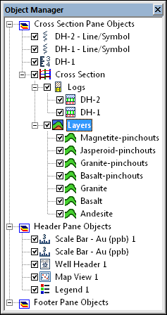
The Object Manager contains a list of all
objects in the cross section view. The
Layers object is selected in this example.
The Cross Section object is created when a new cross section is created with the Cross Section | Create/Add | Create Cross Section command. The Cross Section object controls properties for the entire cross section. This include the spacing for the cross section, the ability to recreate the cross section, and whether the logs are deviated or vertical on the cross section.
The WaterLevel object is created when the cross section is created and contains the water level lines in the cross section. The water levels are added to the cross section by first specifying the Water level table in the Water Level properties for either the Logs object or individual log items. Next the Display water level(s) check box must be checked in the Cross Section properties.
The shared line properties of the water level lines can be edited by
clicking the WaterLevel object
in the Object Manger. To see a
list of all of the individual water level lines in the cross section,
click the  next to WaterLevel in the Object Manager. The individual water
level lines can be edited by clicking on the individual water level object
and making the changes in the Property
Manager. Shared line properties are saved when recreating the cross
section.
next to WaterLevel in the Object Manager. The individual water
level lines can be edited by clicking on the individual water level object
and making the changes in the Property
Manager. Shared line properties are saved when recreating the cross
section.
Strater connects the water level layers specified in the water level table automatically. If you also specify the Water level name column in the Water Level properties, the water level lines will be controlled by the water level names.
An individual water level item can be selected from the WaterLevel list in the Object Manager. Each water level item's properties can be set independently. See the Line Properties topic for information on the water level line properties. Individual water level items can be deleted by selecting the water level item and pressing DELETE.
Changing the line properties for an individual water level line is a layer customization. If you recreate the cross section, the Keep customized layers check box must be checked in the cross section properties to maintain the individual water level line changes.
The Logs object is created when the cross section is created and contains all of the lithology, zone bar, line/symbol, or raster logs that are a part of the cross section. These are the logs defined when the cross section is created, either by the selected well selector line in the map view or by the logs selected in the Create Well Selector dialog.
Some shared log properties of all logs
in the cross section can be set by clicking on the Logs
object. To see a list of all of the individual logs in the cross section,
click the
next to Logs in the Object
Manager. The individual logs can be edited by clicking on the individual
log object and making the changes in the Property
Manager.
To change the order of the logs in the cross section, click on an individual log in the Object Manager and drag it to the desired position. The bottom log in the Object Manager is located on the left side of the cross section. The top log in the Object Manager is located on the right side of the cross section. Click Yes in the warning dialog to automatically recreate the layers.
An individual log item can be selected from the Logs list in the Object Manager. The log's properties can be set separately from all other objects. See the lithology, zone bar, or line/symbol log properties for information on individual log properties. Individual logs can be removed from the cross section by clicking on the log name and pressing the DELETE key on the keyboard.
To change the order of the logs in the cross section, click on an individual log in the Object Manager and drag it to the desired position. The bottom log in the Object Manager is located on the left side of the cross section. The top log in the Object Manager is located on the right side of the cross section. Click Yes in the dialog to automatically recreate the layers.
The Layers object is created
when the cross section is created and contains all of the layers that
are defined by the intervals in the lithology or zone bar logs in the
cross section. The layers can be controlled with a keyword
scheme on the Layers tab in the
Property Manager. The line,
fill, and label
properties for all layers can also be controlled by clicking on the Layers object if a scheme is not
used. The Info tab contains
the number of layers in the cross section. To see a list of all the layers
in the cross section, click the next
to Layers in the
Object Manager. The individual
layers can be edited by clicking on the individual layer name and making
the changes in the Property Manager.
An individual layer item can be selected from the Layers list in the Object Manager. The layer's line and fill properties can be set as part of the scheme on the Layers object, or individually. To set the layer properties individually, be sure to first uncheck the Use Scheme For Line/Fill box on the Layers tab of the Layers object.
To change the order of the layers in the cross section, click on an
individual layer and drag it to the desired position. It is recommended
that the pinchout layers stay above the non-pinchout layers so that the
cross section is drawn correctly. If the layer order is changed and results
in a cross section that is not appropriate, click on the Cross
Section object and click the  button in the Property Manager.
When wells are displayed as deviated, additional layers are displayed in the Object Manager. Each layer is broken into multiple pieces, so that the areas between wells can be individually edited.
If automatic layers are not desired, manual layers can be created using the Connect Logs with Layers, and layer mark Import and Create/Edit commands. When using layer marks, the layer lines and layer fill objects are listed in the Layers list in the Object Manager.
The Well Header object is added by clicking the Cross Section | Create/Add | Add Well Headers command. The well header properties control the items that are displayed in the well header, including the distance between wells, well symbol symbol, and the text that is displayed in the header for each well.
Any log type can be added to the cross section by clicking the appropriate command under the Log menu. These logs are not used in the automatic interpolation of the cross section layers. But, they can be used when picking layer marks. To position these logs in the appropriate spot on the cross section, make sure the appropriate Hole ID is selected for the Hole ID Filter on the Log tab for the log. Then, click the Log | Display | Overlay Logs command to move all of the logs for each borehole directly on top of each other or the Log | Display | Adjoin Logs to move all of the logs for each borehole directly beside each other. When the Reference Datum changes in the Cross Section View Properties, these logs also move, if layers can be found for each log.
The depth method, reference datum, and depth settings for the entire cross section are controlled on the Cross Section View Properties. To edit the view properties, click the View | Display | View Properties command.
See Also