Some cross section properties edit the entire cross section view. These include the well spacing and whether the logs are displayed as deviated. Individual objects can still be changed, but these default properties control all of the objects that have not been specifically changed.
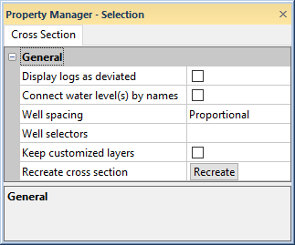
To edit the common cross section properties, click on the Cross Section object in the Object Manager. The properties are listed in the Property Manager.
Set the cross section properties on the Cross Section tab.
Check the box next to the Display logs as deviated to show all deviated logs as non-vertical in the cross section. In addition to checking this box, make sure that the Depth method on the cross section View properties page is set to True Vertical Depth and set the Hole inclination column (or Hole dip column) and Hole azimuth column on the Logs page. To display all wells as vertical, uncheck the Display logs as deviated box.
When displayed as deviated, lithology and zone bar display the log with all properties deviated. Line/symbol logs are displayed with the properties and trace deviated.
Line/symbol logs cannot display grid lines while they are deviated. Variable and depth grid lines are removed when the Display logs as deviated check box is checked. The variable and depth grid line settings are remembered and are displayed automatically when the Display logs as deviated check box is unchecked. Line/symbol logs also cannot display fills when they are deviated. The Logs object and individual line/symbol log item Fill page is removed from the Property Manager when the Display logs as deviated check box is checked. Fill settings are remembered and are displayed automatically if the Display logs as deviated check box is unchecked.
The horizontal location of well headers and scale bars are controlled by the well top. If the cross section Starting borehole depth on the View properties page is different than the well top, the well header and/or scale bars may not be in same location as the visible portion of the log.
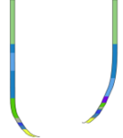
The cross section on the left shows lithology logs as deviated.
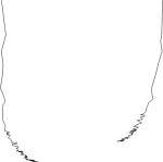
The cross section on the right shows line/symbol logs
as deviated.
If a Water level table has been specified for some or all of the logs on the Water Level page, the water levels can be connect by a line on the cross section by checking the Connect water level(s) by names check box. Strater connects the water level layers specified in the water level table automatically when the water level table does not include a label column. When Strater automatically connects the water levels, the top water level in each well is connected, the second water level in each level is connected, etc. The water level name column is used to specify the water level connections between wells. If you also specify the Water level name column in the Water Level properties, the water level lines will be controlled by the water level names. Water level lines are drawn left to right and will not cross. See the Parts of a Cross Section topic for more information on the WaterLevel object and the individual water level layer items. Uncheck the Connect water level(s) by names check box to remove the water level lines from the cross section.
The Well Spacing sets the method to use to place wells on the page. The options are Proportional and Uniform. Setting the spacing to Proportional makes 1 unit of distance the same between all wells. So, two wells that are 200 units apart will be twice as far apart in the cross section as two wells that are 100 units apart. Setting the spacing to Uniform places all wells an equal distance from all neighboring wells, regardless of the actual distance between wells. To change the spacing, click on the existing option and select the desired option from the list.
When the Display Logs As Deviated option is checked, the Well Spacing is automatically set to Proportional and cannot be changed.
Cross section linked scale bars should only be used when the Well Spacing is set to Proportional. When a linked scale bar is attached to a cross section that has a Proportional well spacing that is changed to Uniform, a warning message appears indicating that the cross section scale bar may not be accurate with the Uniform well spacing. In this case, the distances will not be accurate across the entire cross section. Click Yes to continue changing the Well Spacing to uniform. It is then recommended that the scale bar be deleted. Click No to keep the cross section as Proportional so that the scale bar is accurate.
When a scale bar is added to a cross section that already has Well Spacing set to Uniform, a warning message appears indicating that the scale bar measurement will not be accurate. Click Yes to add the scale bar. Click No to not add the scale bar.
If you have made layer customizations, for example with Reshape, check the Keep customized layers check box to maintain the customizations when recreating the cross section. When the Keep customized layers check box is not checked, the customizations will be discarded if the cross section is recreated.
To recreate the connections between the wells in the cross section, click the Recreate button. Cross section customizations can be maintained when recreating the cross section by checking the Keep customized layers check box. If you have added or removed wells, you may wish to clear the layer customizations. Recreate the cross section without layer customizations by clicking Recreate when the Keep customized layers check box is not checked. A warning message will be displayed when recreating the cross section while Keep customized layers is not checked.
A well selector is automatically added when creating a cross section. You can add logs to the cross section by editing the well selector. To add logs to the cross section:
Click the Cross Section object in the Object Manager.
In the Cross Section page, find the map view for the selected well selector in the Well selectors field. The value in the Well selectors field will display the well names and the location of the well selector in the map view. For example, in the Cross Section_LineLogs.sdg sample file, the Well selectors field displays South Barrow 19 - South Barrow 18 - South Barrow 17 (in Map 1 - Detail).
Click the map view that contains the well selector. To continue the example from step two, we click the Map 1 - Detail document tab or click Map 1 - Detail in the View Manager.
Click the well selector in the Object Manager. The name of the well selector was found in step two.
Click the Edit button on the Well Selector page of the Property Manager.
Add, remove, and/or reorder the wells as desired in the Well Selector Editor.
Click OK.
Return to the cross section view by clicking the document tab or clicking the cross section in the View Manager.
Click the Cross Section object in the Object Manager.
Click the Recreate button in the Recreate cross section field.
The cross section is recreated with the updated well selector.
See Also