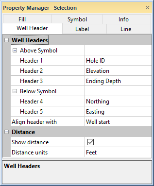
The cross section well header is created with the Cross Section | Create/Add | Add Well Headers command. Click on the Well Header object in the Object Manager and the Well Header tab in the Property Manager to edit the general well header properties.
Edit the text that appears in the cross section well
headers on the Well Header tab in the Property Manager.
The Header 1 text is the first line of text that can be displayed above the symbol in the well header. To set the text, click on the existing option and select the desired option from the list. Click [None] if the line of text should not be created.
The Header 2 text is the second line of text that can be displayed above the symbol in the well header. This text appears above the borehole symbol and below the Header 1 text. To set the text, click on the existing option and select the desired option from the list. Click [None] if the line of text should not be created.
The Header 3 text is the third line of text that can be displayed above the symbol in the well header. This text appears above the borehole symbol and below the Header 2 text. To set the text, click on the existing option and select the desired option from the list. Click [None] if the line of text should not be created.
The Header 4 text is the first line of text that can be displayed below the symbol in the well header. This text appears below the borehole symbol and above the Header 5 text. To set the text, click on the existing option and select the desired option from the list. Click [None] if the line of text should not be created.
The Header 5 text is the second line of text that can be displayed below the symbol in the well header. This text appears below the borehole symbol at the bottom of the well header. To set the text, click on the existing option and select the desired option from the list. Click [None] if the line of text should not be created.
The Align header with property specifies if the well header is in horizontal alignment with the Well start or Well end. The Align header with property also determines the distance value when Show distance is checked. To change the Align header with property, click the current selection and select Well start or Well end from the list.
Check the box next to Show Distance to show distance values between boreholes on the cross section. Uncheck the box to not display distances. When Align header with is set to Well start, the distance value is the XY distance between the well tops. When Align header with is set to Well end, the distance value is the XY distance between the well ends.
The Distance Units option controls the units used to display the distance on the cross section well header. To change the units, click on the existing option and select the desired option from the list. Setting the Units to Automatic reads the units from the coordinate system of the map in the associated map view.
If the units are not specified for the Map, the Column units from the Easting and Northing column in the collars table are used. If the units are different in these columns, the Easting column is used. If only one of the Easting or Northing column has units, that column's units are used. If the Easting and Northing columns do not have column units, a Numeric Suffix can be added in the Format section of the Label page to display the units.
When the column units are not recognized, conversion between units is not done properly. The label will not display properly in this instance.
See Also