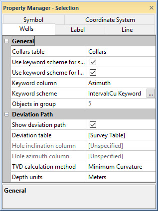
A Wells layer contains the wells and well selector lines in the map. The wells that appear are in the same collars table. Wells maps are created with the Map | Create | Well Map command. Additional Wells maps can be added to the existing map with the Map | Add | Well Layer command. The Wells page of the Property Manager contains general wells properties and deviation path properties.
Each well from the collars table is shown as a symbol, with labels.
The map also shows a well selector as a red line.
The Collars table displays the name of the collars table. To change the collars table, click on the existing collar table name and select the desired collars table from the list. All collars tables in the project will be included in the list.
Check the box next to Use keyword scheme for symbols to use a keyword scheme to assign symbols to the wells. When this box is checked, the options on the Symbol tab are not available and the symbols vary, as determined by the selected Keyword column and Keyword scheme. When this box is unchecked, all symbols are the same and are determined by the symbol properties set on the Symbol page.
The keyword scheme is used by default and is based on the type, keyword, or symbol column found in the collars table. If these columns are not found, the default symbol properties are used for all symbols in the well map.
Check the box next to Use keyword scheme for label font to use a keyword scheme for the font label properties for the wells. When this box is checked, the Font options on the Label tab are not available and the font properties vary, as determined by the selected Keyword column and Keyword scheme. When this box is unchecked, all label font properties are the same and are determined by the font properties set on the Label page.
The Keyword column is the column in the collars table that is used to determine the symbol and font label properties. Any column can be used. To change the column, click on the existing option and select the desired column from the list. If no keyword column is desired, uncheck the box next to Use keyword scheme for symbols or Use keyword scheme for label font options.
The Keyword scheme is the scheme
currently used to determine the symbol or font label properties for all
of the wells in the Wells layer.
To change the scheme, click on the existing scheme. In the list, select
the desired scheme and the wells automatically update to the new scheme
name. Alternatively, click on the scheme name. Click the  to open the Scheme
Editor.
to open the Scheme
Editor.
The Objects in group option lists the number of objects in the currently selected Wells layer. This includes all wells and all well selector lines. This option is not editable.
Check the box next to Show deviation path to turn on the display of deviation lines on the map. Uncheck the box to turn off the deviation lines on the map, showing only the top of the well location.
The Deviation table is the table from which the Hole inclination column (or Hole dip column), and Hole azimuth column are read. Available options are [Collars Table], [Survey Table], and any other depth or interval tables that have already been loaded into the project. [Collars Table] loads the collars table used to create the well location map. The collars table is specified on the Wells tab when a well location map is selected. [Survey Table] loads the information from all survey tables in the project. A well should only be included in a single survey table. Selecting any of the other tables activates the Hole inclination column (or Hole dip column) and the Hole azimuth column. To change the Deviation table, click on the existing option and select the desired option from the list. If no table should be used, uncheck the box next to Show deviation path.
When recorded in a collars table, the inclination (or dip) and azimuth apply to the entire well length. When recorded in a survey table, the inclination (or dip) and azimuth apply from the depth to the next recorded depth. When set to one of the depth or interval tables, each well is updated independently from each other well using the information in the specific tables.
The Hole Inclination Column (or Hole Dip Column) is used in combination with the Hole Azimuth Column to calculate the true vertical depth for the hole. Either Hole Inclination Column or Hole Dip Column is displayed. To control whether inclination or dip is used, click the File | Options command. In the Options dialog, check or uncheck the Use Hole Dip Instead Of Inclination option.
Inclination is the angle the borehole is oriented in degrees and varies from 0 to 180. 0 indicates vertical pointing down, 90 indicates horizontal, and 180 indicates vertical pointing up. Negative and positive inclination values are treated the same for depth calculations. Negative inclination values are treated differently for well path calculations in the cross section and map views. A negative inclination changes the direction (azimuth) to the opposite of the similar positive inclination. For example, the azimuth value of 90 and inclination of 45 describes the same orientation as the azimuth value of 270 and inclination of -45 degrees. Both combinations describe an eastward direction at 45 degrees down from the horizontal plane.
Dip is an alternate method of calculating the angle the borehole is oriented. Dip is oriented in degrees and varies from -90 to 90. -90 indicates vertical pointing down, 0 indicates horizontal, and +90 indicates vertical pointing up.
Azimuth is the compass orientation of the well's deviation, in degrees and varies from 0 (true vertical north) to 360. Azimuth values are measured relative to true north (not grid north in the local coordinate system).
To set the Hole Inclination Column or Hole Dip Column, click on the existing option and select the desired option from the list. Available options are [Unspecified], [From collars table:collars name], [From survey table: survey name], or data columns in the existing Curve Table. When one column is set to unspecified or survey table, the other column automatically changes to the same option. When recorded in a collars table, the inclination/dip and azimuth apply to the entire well length. When recorded in a survey table, the inclination/dip and azimuth apply from the depth to the next recorded depth. When set to one of the columns in the existing table, each log is updated independently from each other log using the information in the specific depth or interval tables. If the Hole Inclination Column for the log is set to [Unspecified], an inclination value of 0 is used for the calculations. No difference will be visible for the log when changing the Depth Method to True Vertical Depth.
When the Show deviation path is checked, the displayed depth value is calculated using the depth from the table and the azimuth and inclination. The TVD calculation method determines how the values are combined to get the true vertical depth. Available options are Tangential, Average Tangential, Balanced Tangential, Radius of Curvature, and Minimum Curvature. The default is Minimum Curvature, which provides a good estimate of the true vertical depth. To change the calculation method, click on the existing option and select the desired option from the list.
Select the depth unit type from the Depth units list. The units selected here should match the units of the depth data in the Deviation table. To change the Depth units, click on the existing option and selected the desired measurement from the list.
Occasionally, a Wells layer will not update properly, leaving a deviation path for the well, but removing the well symbol when changing the visibility of an individual well in the Object Manager. When this happens, there are two things that can be done to make the wells appear correct:
Click on the Wells layer and click the Deviation Path tab in the Property Manager. Uncheck the box next to the Show Deviation Path option. Recheck the box and the well will appear correctly.
Click the File | Options command. Click on General on the left side of the dialog. On the right side, check the box next to Reload Data When Opening Project. Close the file and reopen it. The wells will display properly.
See Also