True Vertical Depth
When boreholes are not completely vertical, the measured depth (MD)
and true vertical depth (TVD) of the borehole are different. The measured
depth is the total distance travelled along the borehole from the starting
point (usually the collar) to the bottom of the borehole. The measured
depth is used in combination with azimuth and inclination or dip information
to calculate
the true vertical depth, the actual depth below the starting point where
a measured value should be displayed.
Inclination or dip and azimuth are indicators of how far off vertical
a borehole is. When recorded in a collars table, the azimuth and inclination
or dip apply to the entire borehole length. When recorded in a survey
table, the azimuth and inclination or dip apply from the depth to the
next recorded depth.
Inclination is the angle the
borehole is oriented in degrees and varies from 0 to 180. 0 indicates
vertical pointing down, 90 indicates horizontal, and 180 indicates vertical
pointing up. Negative and positive inclination values are treated the
same for depth calculations. Negative inclination values are treated differently
for well path calculations in the cross section and map views. A negative
inclination changes the direction (azimuth) to the opposite of the similar
positive inclination. For example, the azimuth value of 90 and inclination
of 45 describes the same orientation as the azimuth value of 270 and inclination
of -45 degrees. Both combinations describe an eastward direction
at 45 degrees down from the horizontal plane.
Dip is an alternate method
of calculating the angle the borehole is oriented. Dip is oriented in
degrees and varies from -90 to 90. -90 indicates vertical pointing down,
0 indicates horizontal, and +90 indicates vertical pointing up.
Azimuth is the compass orientation
of the well's deviation, in degrees and varies from 0 (true vertical north)
to 360. Azimuth values are measured relative to true north (not grid north
in the local coordinate system).
In the borehole view
properties or cross
section view properties, when the Depth
Method is set to True Vertical
Depth, the individual log depths are calculated using the azimuth
and inclination or dip values. These values can be set from a depth, interval,
survey, or collars table. There are three ways to enter the inclination
or dip and azimuth data:
A
single set of azimuth and inclination or dip data can be entered for
each borehole in the collars table. The azimuth and inclination or
dip data would apply to all points throughout the borehole.
A
deviation survey could be imported for each borehole into a survey
table. The deviation or survey data does not have to have the same
sample interval as the wireline or depth/interval data.
Azimuth
and inclination or dip data can be entered for each data point in
the borehole directly in the depth or interval table as additional
columns with the rest of the borehole data.
Once inclination or dip data
is entered into a data table, the Hole
Inclination Column or Hole Dip Column and Hole
Azimuth Column need to be specified for each log in the borehole
view or cross section view in the Property
Manager. When the inclination or dip and azimuth data is entered in
the table and the columns are specified for each log in the view window,
the view window can be set to true vertical depth measurements. Click
on the View | Display |
View Properties command. The view properties are listed in the Property Manager. Change the Depth Method from Measured
Depth (the default) to True Vertical
Depth. All the logs in the view will update with the selected depth
method.
Depth logs are the only log
types that have their own depth method selection, so you can set the depth
scope of the depth log independently of the depth method for the view.
This allows you to create one depth log showing measured depth and another
showing true vertical depth side-by-side. To set the depth log to true
vertical depth, click on the depth log in the Object
Manager or view window to select it. In the Property Manager, set the
Depth Scope to Hole True Vertical Depth.
Example True Vertical Depth
To create boreholes in true vertical depth requires having data for
the borehole that includes azimuth and inclination or dip. The azimuth
and inclination or dip values can be in a survey table, a collars table,
or in the depth table. Once the azimuth and inclination or dip data are
entered, the view window and logs can all be set to display true vertical
depth. This example imports two tables: a survey table with inclination
or dip and azimuth and a depth table. A line/symbol log is created from
the depth table. Two depth logs are then created: one display true vertical
depth and one displays measured depth.
Click
the File | New Project command or click
the  button to open a
new project.
button to open a
new project.
Open
the data tables:
Click the File
| Open Multiple command.
In the Open
Data dialog, click on the Example
Data.xls file in the Samples directory. By default, the
Samples directory is located at C:\Program Files\Golden Software\Strater
5\Samples.
Click Open.
Select the Deviation
Survey sheet.
Press and hold the
CTRL key on the keyboard and select the Depth
sheet.
Click OK.
For the Depth table:
In the Specify
Worksheet Column Definitions dialog, make sure that the
Specify Column Header Row
is checked and set to 1. Click Next.
In the Specify
Data Type and Column Positions dialog, make sure that
the Data type to
Depth (Single Depth)
and that all of the columns are set correctly and click Finish.
For the Deviation
Survey:
In the Specify
Worksheet Column Definitions dialog, make sure that
the Specify Column Header
Row is checked and set to 1. Click Next.
In the Specify
Data Type and Column Positions dialog, set the Data type to Survey.
Make sure all of the columns are set correctly and click Finish.
Click
on the Borehole 1 tab or
click Window | Borehole 1
to return to the borehole view.
Create
a line/symbol log by clicking the Log
| Create Log | Line/Symbol command.
Click near the center
of the log pane to position the line/symbol log.
In the Open
dialog, select Depth
in the Use Current Table
list.
Make sure that Depth is listed in the File name option.
Click
Open.
Set
the line/symbol log to use true vertical depth measurements.
Click on the line/symbol
log in the view window or in the Object
Manager to select it.
In the Property
Manager, click on the Line/Symbol
Log tab.
Next to Hole
Inclination Column or Hole Dip Column, click on [Unspecified]
and select [From survey table]:
Deviation Survey.
Notice that the Hole Azimuth Column automatically
is set to [From survey table]:
Deviation Survey. When using a survey table, the inclination
or dip or dip and azimuth columns must come from the same table.
Create
a depth log by clicking the Log | Create
Log | Depth command.
Click
on the far left side of the page in the log pane to position the first
depth log.
Set
the depth log to use measured depth.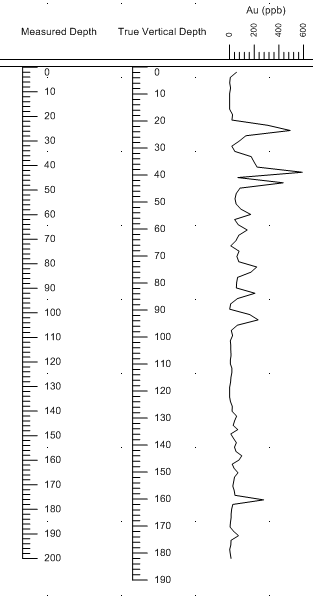
With the depth log selected,
in the Property Manager, click on the
Depth Log tab.
Set the Depth
Scope to
Hole Measured Depth by clicking on the existing
option and select Hole
Measured Depth from
the list.
Next to Hole Inclination
Column or
Hole
Dip Column,
click on [Unspecified] and
select [From survey table]: Deviation Survey.
Notice that the Hole Azimuth Column automatically
is set to [From survey table]:
Deviation Survey. When using a survey table, the inclination
or dip and azimuth columns must come from the same table.
Click
the Draw | Shape | Text command.
Click
above the depth log to position the text.
In
the Text Editor, type Measured Depth and click OK.
Press
ESC on the keyboard to end drawing mode.
Create
a depth log by clicking the Log | Create
Log | Depth command.
Click
between the existing depth log and the line/symbol log to position
the second depth log.
Set
the depth log to use
true vertical depth.
With the new depth
log selected, in the Property
Manager, click on the Depth
Log tab.
Set the Depth
Scope to Hole True Vertical
Depth by clicking on the existing option and select Hole True Vertical Depth from
the list.
Next to Hole
Inclination Column or Hole Dip Column, click on [Unspecified]
and select [From survey table]:
Deviation Survey.
Notice that the Hole Azimuth Column automatically
is set to [From survey table]:
Deviation Survey. When using a survey table, the inclination
or dip and azimuth columns must come from the same table.
Click
the Draw | Shape | Text command.
Click
above the second depth log to position the text.
In
the Text Editor, type True Vertical Depth and click
OK.
Press
ESC on the keyboard to end drawing mode.
Click
the View | Display | View Properties
command to display the borehole
view properties.
Click
on the Measured Depth option
next to Depth Method and
select True Vertical Depth
from the list.
The view is displayed in true vertical depth. The first depth
log shows measured depth and the second depth log shows true vertical
depth. The log is also shown with true vertical depth.
See
Also
True Vertical Depth
Calculation Methods
Borehole View Properties
Cross Section
View Properties
Table Types