
Well construction logs require specific data columns (From, To, Item, Offset, Inner Diameter, and Outer Diameter), a well construction scheme, and a well size. All of these pieces of information work together to create complex well construction logs.
The following data and properties are used in this example.
This example file is used in the following graphic.
Several table columns, a well construction scheme, and
the Well Size are needed to create a well construction log.
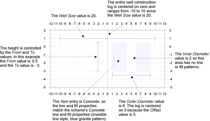
The following diagram explains the association between the data, scheme, well size, and log graphic by showing a well log object based on the above data.
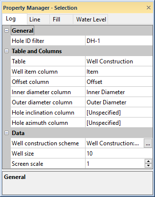
The Well Size is set in the well construction log's Well Construction Properties in the Property Manager. This number can represent any units you wish. The Well Size and the width (as set in the Position/Size toolbar) provide a scaling mechanism for the log's objects. In this example, the Well Size is 20. If the Width of the log is set to 2.00 inches, this means one horizontal inch on the log equals 10 units. The object's Outer Diameter of 8 translates into 0.8 inches on the screen.
The Well Size is also important in determining the position of the objects within the well. The center of the log is zero. Since the Well Size in this example is 20, the numeric positioning range is -10 to 10. The Offset data field controls the horizontal positioning of objects relative to these numbers. In this example, the object's offset is 5, so the object is located 5 units right of center.
Well construction logs require interval data. The interval's From and To columns control the height of the well object. In the diagram above, the object's height is 3.5 units since the From column value is 0.5 and the To column value is -3.
The well object width is controlled by the Outer Diameter column. In this example, the object's width is 8, so the object is displayed on the log as 8 units wide. Since the object has an Offset value of 5 (see the Well Width and Well Object Positioning section above), the item is centered on 5.
Some well objects need "cutouts" for proper display. The Inner Diameter column is a region where no line and fill properties exist for the object. In this example, the object's Inner Diameter is 2, so there is a gap in the fill pattern between 4 and 6 (since the item is centered on 5). The inner diameter is not used with all well property item types.
Well construction schemes control the shape, line properties, and fill properties of the well objects. In this example, the data column's Item entry is Concrete. This entry, called a keyword, matches a keyword in the well construction scheme. In the scheme, the Well Cover scheme item contains a "Standard" shape (filled rectangle), and a 90% Black Horizontal fill pattern.
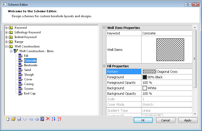
The Well Construction scheme is used to determine the well properties.
When this information is combined you have all the data required to build a well construction log.
The simple well construction log is based on the data displayed above. Note the From and To levels of the log are aligned with 0.5 and -3.0 in the depth log that was added for greater clarity.
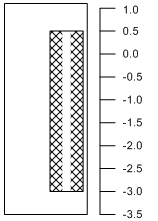
The final well construction log
is based on scheme, Property
Manager, and data table information.
Strater provides many customizable options for well construction logs, including scheme entries to customize screen, casing, cover, and cap styles.
See Also