Strater allows you to make object properties transparent in percentage increments of opacity from 0% to 100%. An opacity value of 0% is completely transparent and 100% opacity is completely opaque.
Transparency is available for the following properties: Fill, Line, Font and Symbol.
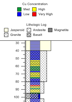
Opacity allows you to overlap and ‘see through’ multiple objects simultaneously. For example, you can display a zone bar log and a lithologic log superimposed on each other. If you add the appropriate legends the result can look like the following:

Two logs can appear superimposed
over each other when you change
the opacity of their properties.
For log objects whose properties are based on schemes, you must change the opacity property of each item in the applied scheme.
In this example we will use the file Example Logs.sdg, which is located in the Samples folder in the Strater installation directory. The standard default directory path is C:\Program Files\Golden Software\Strater 5\Samples.
This is a common opacity function, and is used in the sample image above.
With an open project that contains a log with fill, such as a zone bar log or lithology log, select the log in the log pane. In the sample file Example Logs.sdg click on the Lithology log in the Object Manager or view window.
In the Property Manager click the Log tab.
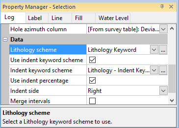
Locate the name of the Lithology scheme. In this example the scheme is Lithology Keyword:

Locate the scheme of the current object to change
the opacity properties of each item in the scheme.
Click the Home |
Display | Scheme Editor command
or click on the name of the scheme and click the  button. The Scheme
Editor opens.
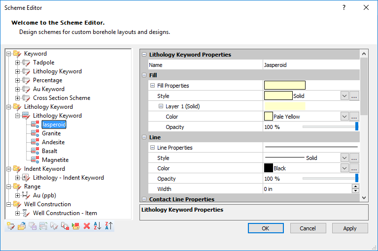
Locate and click the scheme name found in the Scheme Editor. Make sure you are selecting the correct scheme; in this example below there are two schemes named Lithology Keyword but one is in the Keyword scheme category and the other, the one we want, is in the Lithology Keyword scheme category.
Select the first item in the scheme, Jasperoid in this example. The item's properties appear on the right side of the Scheme Editor.

Selecting a scheme item opens the properties for that item; in this example the properties for
the scheme item Jasperoid are displayed.
Under Fill Properties, select the Opacity field and change its opacity value. In this example we are changing the opacity value to30%. If the selected fill style has both a Foreground color and Background color you must change both the Foreground opacity and Background opacity. Stock fill style layers have both a Foreground opacity and Background opacity. Some Image fill style layers have both opacities, but most only have an Opacity property. The opacity for a Gradient fill style layer is set in the Colormap Editor.
|
|
The Jasperoid scheme item uses a Solid layer fill style and has only an Opacity property. |
The Basalt scheme item uses a Stock layer fill style and has both the Foreground opacity and Background opacity properties. |
Click Apply.
Select the next item in the Scheme Editor and repeat the process of changing the Opacity or both the Foreground opacity property and Background opacity depending on the fill style.
When the opacity property for all items in the scheme have been modified, click OK in the Scheme Editor.
To verify that the opacity of the log is acceptable, click on the log and drag it so that overlaps another log. If the log moves beneath the other log, click the Arrange | Move | To Front command.

This is a lithology log with 30% opacity
overlapping a percentage log.
It is possible that the first opacity value that is entered is not the best value for the desired result. Repeat the above steps to modify the percentage of opacity to give the most satisfying result.
To change the opacity of the text, line, and symbol properties follow the same instructions as for the fill pattern. For example, to change the opacity of symbols (in this example, the Class Post Log 1 in the file Example Logs.sdg) you:
Select the object.
Locate the range scheme name used by the object in the Property Manager.
Click the Home |
Display | Scheme Editor command or click on the name of the
scheme and click the  button.
The Scheme Editor dialog opens.
Expand the desired scheme.
Select the desired scheme item.
Locate the Symbols Properties section on the right side of the Scheme Editor.
Change the Fill opacity and Line opacity to the desired level and click Apply.
Make any further changes, and click OK to close the Scheme Editor.
Click on the object and move it over another object to verify the opacity change.
Use the same instructions above for Font and Line opacity properties.
Some objects, such as line/symbol logs, do not have schemes. For these objects the opacity fields are located in the Property Manager Line, Fill, Symbol, and Font sections rather than the Scheme Editor.