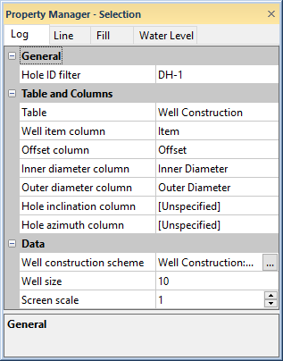
The Log page in the Property Manager includes options for defining the data table and well size for a well construction log. To view and edit well construction log properties, click on the well construction log in the view window or Object Manager to select the log. Then, click on the Log tab in the Property Manager.
Edit well construction log properties on the
Well Construction tab in the Property Manager.
The Hole ID filter is used to select the borehole to associate with this log. Only those Hole IDs that are currently associated with data tables in this project are listed. To change the Hole ID Filter, click on the existing Hole ID and select the desired Hole ID from the list. The log automatically updates to show the new borehole.
When the Logs object is selected in a cross section view, the Hole ID filter is not available. To set a specific log to a particular Hole ID, click on that individual log and set the Hole ID filter to the appropriate log.
Use the Table to define the data table for the well construction log. The table type must be a well construction table type.
The Well item column is the column in the selected Table that sets the well construction component. When the Table is changed to another table, the Well item column list is automatically updated to display the column names in the newly selected table. To change the column, click on the existing column name next to Well item column and select the desired column from the list.
The Well item column is used for linking the table item name to the matching item in a well construction scheme. This column is used to define shapes, fill patterns, etc. for the various well construction components.
Use the Offset column to select the column in the well table that contains the horizontal offsets for the item within the well construction log. The width of the log is based on the Well size, with zero at the center of the log. For example, if the Well size is 20, an offset value of -5 places the well item 5 units to the left of center of the log. To change the offset column, click on the existing column name and select the desired column from the list.
Use the Inner diameter column to select the column in the well table that contains information to cut a section out of the middle of the items so that it is line- and fill-free. To change the inner diameter column, click on the existing column name and select the desired column from the list.
Use the Outer diameter column to select the column in the well table that contains the outer size (width) of the items. To change the outer diameter column, click on the existing column name and select the desired column from the list.
The Hole inclination column (or Hole dip column) is used in combination with the Hole azimuth column to calculate the true vertical depth for the hole. Either Hole inclination column or Hole dip column is displayed. To control whether inclination or dip is used, click the File | Options command. In the Options dialog, check or uncheck the Use Hole dip instead of inclination option.
Inclination is the angle the borehole is oriented in degrees and varies from 0 to 180. 0 indicates vertical pointing down, 90 indicates horizontal, and 180 indicates vertical pointing up. Negative and positive inclination values are treated the same for depth calculations. Negative inclination values are treated differently for well path calculations in the cross section and map views. A negative inclination changes the direction (azimuth) to the opposite of the similar positive inclination. For example, the azimuth value of 90 and inclination of 45 describes the same orientation as the azimuth value of 270 and inclination of -45 degrees. Both combinations describe an eastward direction at 45 degrees down from the horizontal plane.
Dip is an alternate method of calculating the angle the borehole is oriented. Dip is oriented in degrees and varies from -90 to 90. -90 indicates vertical pointing down, 0 indicates horizontal, and +90 indicates vertical pointing up.
Azimuth is the compass orientation of the well's deviation, in degrees and varies from 0 (true vertical north) to 360. Azimuth values are measured relative to true north (not grid north in the local coordinate system).
To set the Hole inclination column or Hole dip column, click on the existing option and select the desired option from the list. Available options are [Unspecified], [From collars table:collars name], [From survey table: survey name], or data columns in the selected Lithology table. When one column is set to unspecified or survey table, the other column automatically changes to the same option. When recorded in a collars table, the inclination/dip and azimuth apply to the entire well length. When recorded in a survey table, the inclination/dip and azimuth apply from the depth to the next recorded depth. When set to one of the columns in the existing table, each log is updated independently from each other log using the information in the specific depth or interval tables. If the Hole inclination column for the log is set to [Unspecified], an inclination value of 0 is used for the calculations. No difference will be visible for the log when changing the Depth method to True vertical depth.
The Well construction scheme
is the scheme
that determines the shape, fill, and line properties of each item in the
well construction log. The selected
scheme should contain items that match the keyword text in the Well
item column. To change the scheme, click on the existing scheme
name and select the desired scheme from the list. Click the  next to the scheme name
to open the Scheme Editor,
where the scheme can be created or edited.
next to the scheme name
to open the Scheme Editor,
where the scheme can be created or edited.
The Well size is a scaling factor that defines the width of the log contents. Strater scales the widths of the well construction items based on this value. All diameter and offset values in the log are based on this dimension. Therefore, it is very important to specify an appropriate value here and it is also important to specify the appropriate diameters in the log data. For example, if the Well size is set to 17, a diameter value of 8.5 in the data table would represent half the width of the log. To change the well size, highlight the existing value and type a new value. Press ENTER on the keyboard to make the change.
The Screen scale setting is used for the screen items. The Screen scale controls the scaling offset and size of the pattern. The Screen scale varies between 0.1 and 2.0 inches (0.254 and 5.08 centimeters.) For small wells, for example well construction logs only six inches long, the Screen scale may require a smaller scale setting, around 0.5 to show enough lines in the screen zone. For longer well construction logs, a value of one or higher may be necessary to make the lines separate.
See Also