Reshape
Click the Draw | Tools | Reshape
command to move, add, or delete vertices from polylines and polygons.
The Draw | Tools | Reshape command
is also used to edit cross
section connections.
Entering the Reshape Mode
Click on the polyline, polygon, or cross section layers either in the
Object Manager or the view window
to select the object. Click the Draw
| Tools | Reshape command or right-click on the object and choose
Reshape to enter the reshape mode.
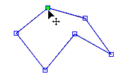
After selecting Reshape, the cursor
changes to  to indicate reshape
mode. For a cross section, click on the layer name in the Object
Manager or in the cross section view window and click the Draw | Tools | Reshape command to
edit a specific layer. The object's vertices appear as hollow blue squares.
Reshape mode is persistent and you can reshape multiple items until you
exit the reshape mode. After you reshape an object, select another object
to reshape or exit reshape mode.
to indicate reshape
mode. For a cross section, click on the layer name in the Object
Manager or in the cross section view window and click the Draw | Tools | Reshape command to
edit a specific layer. The object's vertices appear as hollow blue squares.
Reshape mode is persistent and you can reshape multiple items until you
exit the reshape mode. After you reshape an object, select another object
to reshape or exit reshape mode.
When Reshape
is activated the lines of the
object turns blue, with blue squares for vertices.
Exiting the Reshape Mode
To exit reshape mode and save the changes made to the object, press
ENTER on the keyboard, press ESC on the keyboard, select another command
or toolbar button, or double-click in the white space in the view window.
Selecting Vertices
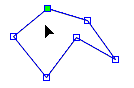
Left-click
on a vertex to select it. The selected vertex is indicated by a solid
cyan square.
To
select the first vertex, press the HOME key. To select the last vertex,
press the END key.
To
shift the selected vertices forward by one position, press the TAB
key. To shift the selected vertices backward by one position, hold
the SHIFT key and press the TAB key.
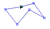
Hovering
the mouse over an unselected vertex will display a grey highlight
around the vertex indicating it may be selected or dragged.
The
cursor will change to  when it is over
a vertex to indicate the vertex may be selected or dragged.
when it is over
a vertex to indicate the vertex may be selected or dragged.

A selected vertex
turns cyan.
Deselecting Vertices
All vertices can be deselected by clicking in an unused space in the
view window.
Moving Vertices
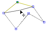
When a vertex is selected and the cursor displays as ,
hold the left mouse button down and drag the vertex to a new location.
As the vertex is dragged its prior position is still visible as a cyan
square. The location of the former line segments are displayed in
yellow, and the current location of the line segments is displayed in
black. Release the left mouse button to place the vertex in the new location.
Alternatively, place the cursor over the vertex, hold the SPACEBAR, and
use the ARROW keys on the keyboard to move the vertex to a new location.
Click on a vertex and drag it to the new location. Release
the mouse button and the vertex is moved.
Undo Moving Vertices
Each individual edit can be undone using the Home
| Undo | Undo command.
Adding Vertices
To enter insert mode, hold down the CTRL key. The cursor will change
to  . Left-click anywhere in the
view window, or on the existing object and a new node will be added at
that location to the closes point on the existing object.
. Left-click anywhere in the
view window, or on the existing object and a new node will be added at
that location to the closes point on the existing object.
Deleting Vertices
To delete a vertex, select the vertex and press the DELETE key on the
keyboard.
Unlinking Vertices
If two or more vertices are linked together, you can unlink them by
pressing the SHIFT key on the keyboard, selecting one vertex and moving
it to a new location.
Linking Vertices
If two or more vertices should be linked together, you can press the
SHIFT and ALT keys on the keyboard. Then, click on the first vertex and
drag it near the other vertex. The point will snap to the nearby point.
Panning
While in reshape mode you can move the page by holding down the
left mouse button in an area where there are no vertices and dragging
the mouse.
Status Bar
When the reshape tool is active, the status bar displays tips on reshaping
objects on the far left side. The fourth section indicates how far the
selected vertex has been moved.

The far left side of the status bar shows tips on how
to reshape items. The fourth section shows
how far the vertex has been moved (4.50 inches to the
right in the X direction and 4.62 inches down in the Y direction).
To Reshape a Polyline or Polygon
To edit a polyline or polygon:
Click
on the polyline or polygon in the view window or Object
Manager to select it.
Click
the Draw | Tools | Reshape
command.
The
cursor changes to and all the vertices in the
selected polyline or polygon appear as small hollow squares.
To
move a vertex, left-click on the vertex with the mouse and drag it
to a new location.
To
add a vertex, hold down the CTRL key and click the area on the polygon
or polyline where the point should be added.
To
delete a vertex, click on the vertex to delete and press the DELETE
key on the keyboard.
After
reshaping the object, press the ENTER or ESC key to exit edit mode.
To Edit a Cross Section Layer
Cross section layers can be edited with the Draw
| Tools | Reshape command. To enter the reshape mode, click on
any of the layers in the cross section view window or click on the specific
layer to edit in the Object Manager.
Click the Draw | Tools | Reshape
command to enter reshape mode. To change the shape of the
layer:
Click
on any of the vertices, indicated by the hollow blue squares.
Hold
down the left mouse button and drag the vertex to the new location.
If
the vertex is shared between different layers and you only want to
move it for one layer, press and hold the SHIFT key on the keyboard.
Click on the vertex and drag it to the desired location. The vertex
only moves for the selected layer. This is very useful for pinchouts
that connect.
If
a vertex should be shared between different layers, press and hold
the SHIFT and ALT keys on the keyboard. Click on the vertex and drag
it near the other vertex. The vertices will snap together and be linked.
To
add a vertex, hold down the CTRL key on the keyboard and click the
area on the layer to add the point.
To
delete a vertex, click on the vertex and press the DELETE key on the
keyboard.
To
snap a vertex to the closest point of another layer, click on the
vertex. Hold the left mouse button down and begin moving the vertex.
Press the ALT key on the keyboard and the vertex snaps to the closest
point of the layer nearest the cursor.
After
reshaping the layer, click on another layer to select it.
Press
ESC on the keyboard or click on Cross
Section, Logs, or Layers
object in the Object
Manager to end reshape mode.
See Also
Draw
Menu Commands
Polygon
Polyline
Cross
Section View
Cross
Section Layers